- 您现在的位置:买卖IC网 > Sheet目录2001 > ISL12028IVZ (Intersil)IC RTC/CALENDAR EEPROM 14-TSSOP
26
FN8233.9
November 30, 2010
.
Alarm Operation Examples
Following, are examples of both Single Event and periodic
Interrupt Mode alarms.
EXAMPLE 1
Alarm 0 set with single interrupt (IM = ”0”)
A single alarm will occur on January 1 at 11:30am.
A. Set Alarm 0 registers as follows:
B. Also the AL0E bit must be set as follows:
After these registers are set, an alarm will be generated when
the RTC advances to exactly 11:30am on January 1 (after
seconds changes from 59 to 00) by setting the AL0 bit in the
status register to “1” and also bringing the IRQ/FOUT output
low.
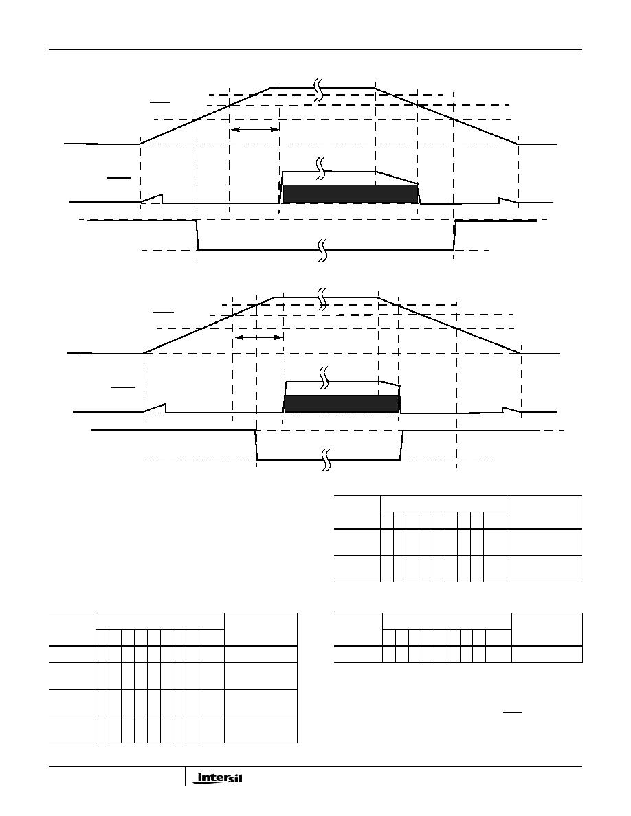
VRESET(2.63V)
RESET
VTRIP
VDD
tPURST
(2.2V)
IBAT
(BATTERY BACKUP MODE)
(VDD POWER, VBAT NOT CONNECTED)
FIGURE 29. EXAMPLE RESET OPERATION IN MODE A OR C
VBAT(3.0V)
I2C-BUS ACTIVE
VRESET (2.63V)
RESET
VTRIP
VDD
(2.2V)
IBAT
(BATTERY BACKUP MODE)
FIGURE 30. RESET OPERATION IN MODE D
VBAT (3.0V)
I2C-BUS ACTIVE
tPURST
ALARM0
REGISTER
BIT
DESCRIPTION
76
543210
HEX
SCA0
00
000000
00h
Seconds disabled
MNA0
10
110000
B0h Minutes set to 30,
enabled
HRA0
1
0
010001
91h
Hours set to 11,
enabled
DTA0
10
000001
81h
Date set to 1,
enabled
MOA0
1
0000001
81h
Month set to 1,
enabled
DWA0
0
0000000
00h
Day of week
disabled
CONTROL
REGISTER
BIT
DESCRIPTION
765
43210
HEX
INT
001
00000
x0hEnable Alarm
ALARM0
REGISTER
BIT
DESCRIPTION
7
6543210
HEX
ISL12028, ISL12028A
发布紧急采购,3分钟左右您将得到回复。
相关PDF资料
ISL12029IVZ
IC RTC/CALENDAR EEPROM 14-TSSOP
ISL12030IBZ
IC RTC/CALENDAR EEPROM 8-SOIC
ISL12032IVZ
IC RTC LP BATT BACK SRAM 14TSSOP
ISL12057IUZ
IC RTC/CALENDAR I2C 8-MSOP
ISL12058IUZ
IC RTC/CALENDAR I2C-BUS 8-MSOP
ISL12059IBZ
IC RTC/CALENDAR I2C-BUS 8-SOIC
ISL12082IUZ
IC RTC I2C LO-POWER 10-MSOP
ISL1208IU8-TK
IC RTC/CALENDAR I2C 8-MSOP
相关代理商/技术参数
ISL12028IVZ-T
功能描述:实时时钟 REAL TIME CLKRTC W/ EPROM IN 14LD T RoHS:否 制造商:Microchip Technology 功能:Clock, Calendar. Alarm RTC 总线接口:I2C 日期格式:DW:DM:M:Y 时间格式:HH:MM:SS RTC 存储容量:64 B 电源电压-最大:5.5 V 电源电压-最小:1.8 V 最大工作温度:+ 85 C 最小工作温度: 安装风格:Through Hole 封装 / 箱体:PDIP-8 封装:Tube
ISL12029
制造商:INTERSIL 制造商全称:Intersil Corporation 功能描述:Real Time Clock/Calendar with I2C Bus? and EEPROM
ISL12029_10
制造商:INTERSIL 制造商全称:Intersil Corporation 功能描述:Real Time Clock/Calendar with I2C Busa?¢ and EEPROM
ISL12029_1012
制造商:INTERSIL 制造商全称:Intersil Corporation 功能描述:Real Time Clock/Calendar with I2C Bus? and EEPROM
ISL12029A
制造商:INTERSIL 制造商全称:Intersil Corporation 功能描述:Real Time Clock/Calendar with I2C Bus? and EEPROM
ISL12029AIB27Z
功能描述:实时时钟 REAL TIME CLKRTC W/ EPROM 2 63VSET 14 RoHS:否 制造商:Microchip Technology 功能:Clock, Calendar. Alarm RTC 总线接口:I2C 日期格式:DW:DM:M:Y 时间格式:HH:MM:SS RTC 存储容量:64 B 电源电压-最大:5.5 V 电源电压-最小:1.8 V 最大工作温度:+ 85 C 最小工作温度: 安装风格:Through Hole 封装 / 箱体:PDIP-8 封装:Tube
ISL12029AIB27Z-T
功能描述:实时时钟 REAL TIME CLKRTC W/ EPROM 2 63VSET 14 RoHS:否 制造商:Microchip Technology 功能:Clock, Calendar. Alarm RTC 总线接口:I2C 日期格式:DW:DM:M:Y 时间格式:HH:MM:SS RTC 存储容量:64 B 电源电压-最大:5.5 V 电源电压-最小:1.8 V 最大工作温度:+ 85 C 最小工作温度: 安装风格:Through Hole 封装 / 箱体:PDIP-8 封装:Tube
ISL12029AIV27Z
功能描述:实时时钟 REAL TIME CLKRTC W/ EPROM 2 63VSET 14 RoHS:否 制造商:Microchip Technology 功能:Clock, Calendar. Alarm RTC 总线接口:I2C 日期格式:DW:DM:M:Y 时间格式:HH:MM:SS RTC 存储容量:64 B 电源电压-最大:5.5 V 电源电压-最小:1.8 V 最大工作温度:+ 85 C 最小工作温度: 安装风格:Through Hole 封装 / 箱体:PDIP-8 封装:Tube